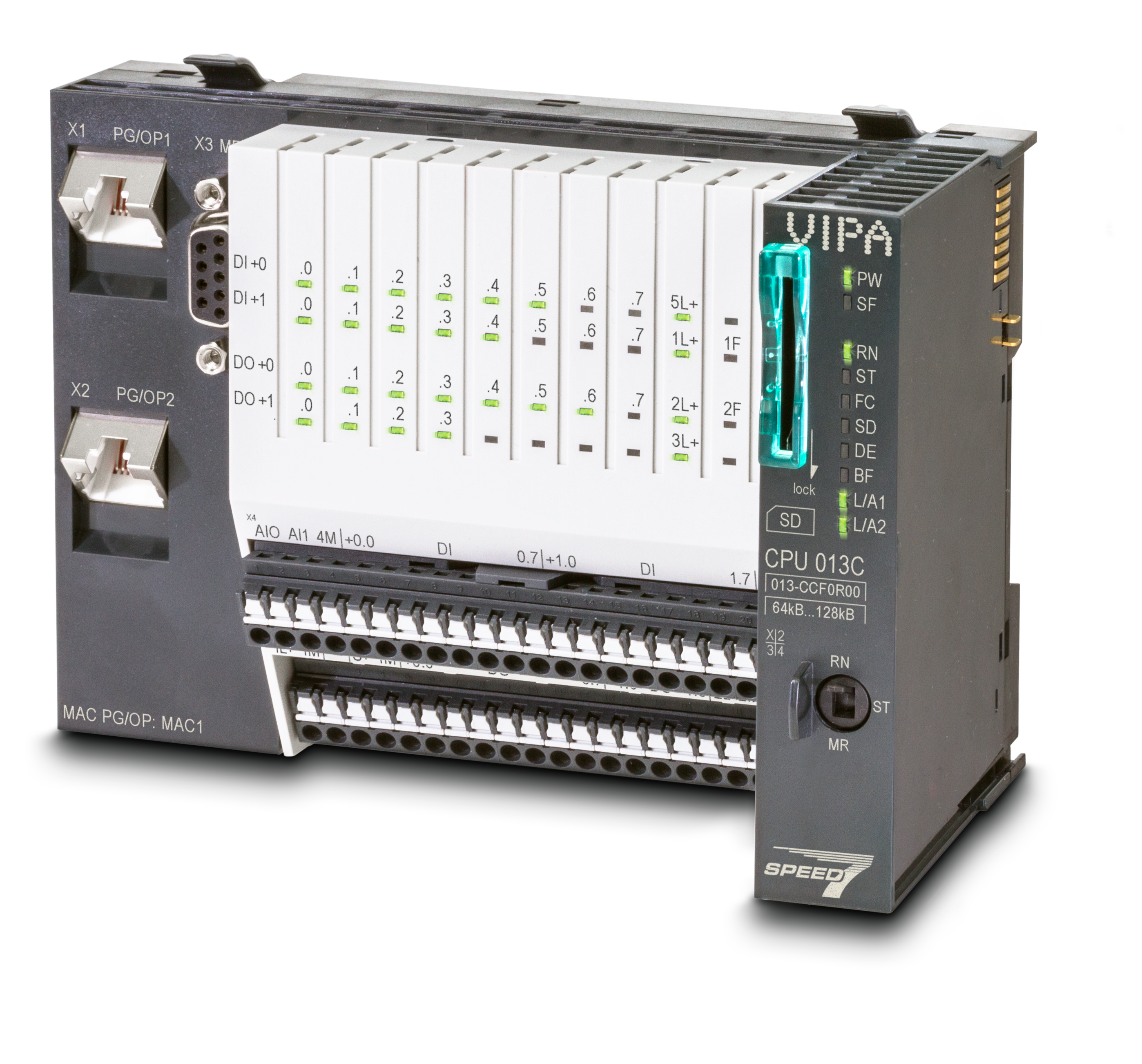
CPU 013
013-CCF0R00 - CPUs | CPUs STEP7 programmable, C class
Order no. |
013-CCF0R00 |
| Type | CPU 013C |
| Module ID | - |
General information |
|
| Note | - |
| Features | Powered by SPEED7 Work memory [KB]: 64...128 Onboard 16x DI / 12x DO / 2x AI [voltage 0...10 V] ] / 4x Counter / 2x [PWM/Pulse Train] Interface [2x RJ45]: active Ethernet PG/OP communication with DHCP support, switch, ModbusTCP master/slave, openCommunication, I-Device, PROFINET IO controller (8 devices) Interface [RS485]: MPI, PtP: ASCII, STX/ETX, 3964 (R), USS master, Modbus master/slave Optional: PROFIBUS master/slave Web server SD card slot with locking, up to 64 expansion modules, configurable with SPEED7 Studio, SIMATIC Manager and TIA Portal |
Technical data power supply |
|
| Power supply (rated value) | DC 24 V |
| Power supply (permitted range) | DC 20.4...28.8 V |
| Reverse polarity protection | ![]() |
| Current consumption (no-load operation) | 120 mA |
| Current consumption (rated value) | 360 mA |
| Inrush current | 3 A |
| I²t | 0.1 A²s |
| Max. current drain at backplane bus | 1 A |
| Max. current drain load supply | 6 A |
| Power loss | 7 W |
Technical data digital inputs |
|
| Number of inputs | 16 |
| Cable length, shielded | 1000 m |
| Cable length, unshielded | 600 m |
| Rated load voltage | DC 24 V |
| Reverse polarity protection of rated load voltage | ![]() |
| Current consumption from load voltage L+ (without load) | 25 mA |
| Rated value | DC 24 V |
| Input voltage for signal "0" | DC 0...5 V |
| Input voltage for signal "1" | DC 15...28.8 V |
| Input voltage hysteresis | - |
| Signal logic input | Sinking input |
| Frequency range | - |
| Input resistance | - |
| Input current for signal "1" | 3 mA |
| Connection of Two-Wire-BEROs possible | ![]() |
| Max. permissible BERO quiescent current | 0.5 mA |
| Input delay of "0" to "1" | 3 µs – 15 ms / 0.5 ms – 15 ms |
| Input delay of "1" to "0" | 3 µs – 15 ms / 0.5 ms – 15 ms |
| Number of simultaneously utilizable inputs horizontal configuration | 16 |
| Number of simultaneously utilizable inputs vertical configuration | 16 |
| Input characteristic curve | IEC 61131-2, type 1 |
| Initial data size | 16 Bit |
Technical data digital outputs |
|
| Number of outputs | 12 |
| Cable length, shielded | 1000 m |
| Cable length, unshielded | 600 m |
| Rated load voltage | DC 24 V |
| Reverse polarity protection of rated load voltage | ![]() |
| Current consumption from load voltage L+ (without load) | 20 mA |
| Total current per group, horizontal configuration, 40°C | 6 A |
| Total current per group, horizontal configuration, 60°C | 6 A |
| Total current per group, vertical configuration | 6 A |
| Output voltage signal "1" at min. current | L+ (-0.8 V) |
| Output voltage signal "1" at max. current | L+ (-0.8 V) |
| Output current at signal "1", rated value | 0.5 A |
| Signal logic output | Sourcing output |
| Output current, permitted range to 40°C | 5 mA to 0.6 A |
| Output current, permitted range to 60°C | 5 mA to 0.6 A |
| Output current at signal "0" max. (residual current) | 0.5 mA |
| Output delay of "0" to "1" | 2 µs / 30 µs |
| Output delay of "1" to "0" | 3 µs / 175 µs |
| Minimum load current | - |
| Lamp load | 10 W |
| Parallel switching of outputs for redundant control of a load | not possible |
| Parallel switching of outputs for increased power | not possible |
| Actuation of digital input | ![]() |
| Switching frequency with resistive load | max. 1000 Hz |
| Switching frequency with inductive load | max. 0.5 Hz |
| Switching frequency on lamp load | max. 10 Hz |
| Internal limitation of inductive shut-off voltage | L+ (-45 V) |
| Short-circuit protection of output | yes, electronic |
| Trigger level | 1 A |
| Number of operating cycle of relay outputs | - |
| Switching capacity of contacts | - |
| Output data size | 12 Bit |
Technical data analog inputs |
|
| Number of inputs | 2 |
| Cable length, shielded | 200 m |
| Rated load voltage | - |
| Reverse polarity protection of rated load voltage | - |
| Current consumption from load voltage L+ (without load) | - |
| Voltage inputs | ![]() |
| Min. input resistance (voltage range) | 100 kΩ |
| Input voltage ranges | 0 V ... +10 V |
| Operational limit of voltage ranges | +/-3.5% |
| Operational limit of voltage ranges with SFU | - |
| Basic error limit voltage ranges | +/-3.0% |
| Basic error limit voltage ranges with SFU | - |
| Destruction limit voltage | max. 30V |
| Current inputs | - |
| Max. input resistance (current range) | - |
| Input current ranges | - |
| Operational limit of current ranges | - |
| Operational limit of current ranges with SFU | - |
| Basic error limit current ranges | - |
| Radical error limit current ranges with SFU | - |
| Destruction limit current inputs (electrical current) | - |
| Destruction limit current inputs (voltage) | - |
| Resistance inputs | - |
| Resistance ranges | - |
| Operational limit of resistor ranges | - |
| Operational limit of resistor ranges with SFU | - |
| Basic error limit | - |
| Basic error limit with SFU | - |
| Destruction limit resistance inputs | - |
| Resistance thermometer inputs | - |
| Resistance thermometer ranges | - |
| Operational limit of resistance thermometer ranges | - |
| Operational limit of resistance thermometer ranges with SFU | - |
| Basic error limit thermoresistor ranges | - |
| Basic error limit thermoresistor ranges with SFU | - |
| Destruction limit resistance thermometer inputs | - |
| Thermocouple inputs | - |
| Thermocouple ranges | - |
| Operational limit of thermocouple ranges | - |
| Operational limit of thermocouple ranges with SFU | - |
| Basic error limit thermoelement ranges | - |
| Basic error limit thermoelement ranges with SFU | - |
| Destruction limit thermocouple inputs | - |
| Programmable temperature compensation | - |
| External temperature compensation | - |
| Internal temperature compensation | - |
| Technical unit of temperature measurement | - |
| Resolution in bit | 12 |
| Measurement principle | successive approximation |
| Basic conversion time | 0.5 ms |
| Noise suppression for frequency | 40 dB |
| Initial data size | 4 Byte |
Technical data analog outputs |
|
| Number of outputs | - |
| Cable length, shielded | - |
| Rated load voltage | - |
| Reverse polarity protection of rated load voltage | - |
| Current consumption from load voltage L+ (without load) | - |
| Voltage output short-circuit protection | - |
| Voltage outputs | - |
| Min. load resistance (voltage range) | - |
| Max. capacitive load (current range) | - |
| Max. inductive load (current range) | - |
| Output voltage ranges | - |
| Operational limit of voltage ranges | - |
| Basic error limit voltage ranges with SFU | - |
| Destruction limit against external applied voltage | - |
| Current outputs | - |
| Max. in load resistance (current range) | - |
| Max. inductive load (current range) | - |
| Typ. open circuit voltage current output | - |
| Output current ranges | - |
| Operational limit of current ranges | - |
| Radical error limit current ranges with SFU | - |
| Destruction limit against external applied voltage | - |
| Settling time for ohmic load | - |
| Settling time for capacitive load | - |
| Settling time for inductive load | - |
| Resolution in bit | - |
| Conversion time | - |
| Substitute value can be applied | - |
| Output data size | - |
Technical data counters |
|
| Number of counters | 4 |
| Counter width | 32 Bit |
| Maximum input frequency | 100 kHz |
| Maximum count frequency | 400 kHz |
| Mode incremental encoder | ![]() |
| Mode pulse / direction | ![]() |
| Mode pulse | ![]() |
| Mode frequency counter | ![]() |
| Mode period measurement | ![]() |
| Gate input available | ![]() |
| Latch input available | ![]() |
| Reset input available | - |
| Counter output available | ![]() |
Load and working memory |
|
| Load memory, integrated | 128 KB |
| Load memory, maximum | 128 KB |
| Work memory, integrated | 64 KB |
| Work memory, maximal | 128 KB |
| Memory divided in 50% program / 50% data | ![]() |
| Memory card slot | SD/MMC-Card with max. 2 GB |
Hardware configuration |
|
| Racks, max. | 5 |
| Modules per rack, max. | total max. 64 minus number line extensions |
| Number of integrated DP master | - |
| Number of DP master via CP | - |
| Operable function modules | 64 |
| Operable communication modules PtP | 64 |
| Operable communication modules LAN | - |
Status information, alarms, diagnostics |
|
| Status display | yes |
| Interrupts | yes |
| Process alarm | yes |
| Diagnostic interrupt | yes |
| Diagnostic functions | yes, parameterizable |
| Diagnostics information read-out | possible |
| Supply voltage display | green LED |
| Group error display | red SF LED |
| Channel error display | red LED per group |
Isolation |
|
| Between channels | ![]() |
| Between channels of groups to | 16 |
| Between channels and backplane bus | ![]() |
| Between channels and power supply | - |
| Max. potential difference between circuits | DC 75 V/ AC 50 V |
| Max. potential difference between inputs (Ucm) | - |
| Max. potential difference between Mana and Mintern (Uiso) | - |
| Max. potential difference between inputs and Mana (Ucm) | - |
| Max. potential difference between inputs and Mintern (Uiso) | - |
| Max. potential difference between Mintern and outputs | - |
| Insulation tested with | DC 500 V |
Command processing times |
|
| Bit instructions, min. | 0.02 µs |
| Word instruction, min. | 0.02 µs |
| Double integer arithmetic, min. | 0.02 µs |
| Floating-point arithmetic, min. | 0.12 µs |
Timers/Counters and their retentive characteristics |
|
| Number of S7 counters | 512 |
| S7 counter remanence | adjustable 0 up to 256 |
| S7 counter remanence adjustable | C0 .. C7 |
| Number of S7 times | 512 |
| S7 times remanence | adjustable 0 up to 256 |
| S7 times remanence adjustable | not retentive |
Data range and retentive characteristic |
|
| Number of flags | 8192 Byte |
| Bit memories retentive characteristic adjustable | adjustable 0 up to 256 |
| Bit memories retentive characteristic preset | MB0 .. MB15 |
| Number of data blocks | 1024 |
| Max. data blocks size | 64 KB |
| Max. local data size per execution level | 4096 Byte |
Blocks |
|
| Number of OBs | 22 |
| Number of FBs | 1024 |
| Number of FCs | 1024 |
| Maximum nesting depth per priority class | 16 |
| Maximum nesting depth additional within an error OB | 4 |
Time |
|
| Real-time clock buffered | ![]() |
| Clock buffered period (min.) | 30 d |
| Accuracy (max. deviation per day) | 10 s |
| Number of operating hours counter | 8 |
| Clock synchronization | ![]() |
| Synchronization via MPI | Master/Slave |
| Synchronization via Ethernet (NTP) | no |
Address areas (I/O) |
|
| Input I/O address area | 2048 Byte |
| Output I/O address area | 2048 Byte |
| Input process image maximal | 2048 Byte |
| Output process image maximal | 2048 Byte |
| Digital inputs | 16224 |
| Digital outputs | 16256 |
| Digital inputs central | 528 |
| Digital outputs central | 524 |
| Integrated digital inputs | 16 |
| Integrated digital outputs | 12 |
| Analog inputs | 1015 |
| Analog outputs | 1015 |
| Analog inputs, central | 514 |
| Analog outputs, central | 256 |
| Integrated analog inputs | 2 |
| Integrated analog outputs | - |
Technical data encoder supply |
|
| Number of outputs | 1 |
| Output voltage (typ) | L+ (-1.5 V) |
| Output voltage (rated value) | 300 mA |
| Short-circuit protection | yes, electronic |
| Binding of potential | Power supply of PLC |
Communication functions |
|
| PG/OP channel | ![]() |
| Global data communication | ![]() |
| Number of GD circuits, max. | 8 |
| Size of GD packets, max. | 54 Byte |
| S7 basic communication | ![]() |
| S7 basic communication, user data per job | 76 Byte |
| S7 communication | ![]() |
| S7 communication as server | ![]() |
| S7 communication as client | - |
| S7 communication, user data per job | 160 Byte |
| Number of connections, max. | 32 |
PWM data |
|
| PWM channels | 2 |
| PWM time basis | 1 µs / 0.1 ms / 1 ms |
| Period length | 50µs...65.535ms / 0.1...87ms / 1...87ms |
| Minimum pulse width | 0...0.5 * Period duration |
| Type of output | Highside |
Functionality Sub-D interfaces |
|
| Type | X3 |
| Type of interface | RS485 |
| Connector | Sub-D, 9-pin, female |
| Electrically isolated | ![]() |
| MPI | ![]() |
| MP²I (MPI/RS232) | - |
| DP master | optional |
| DP slave | optional |
| Point-to-point interface | ![]() |
| 5V DC Power supply | max. 90mA, isolated |
| 24V DC Power supply | max. 100mA, non-isolated |
| Type | - |
| Type of interface | - |
| Connector | - |
| Electrically isolated | - |
| MPI | - |
| MP²I (MPI/RS232) | - |
| DP master | - |
| DP slave | - |
| Point-to-point interface | - |
| 5V DC Power supply | - |
| 24V DC Power supply | - |
Functionality MPI |
|
| Number of connections, max. | 32 |
| PG/OP channel | ![]() |
| Routing | ![]() |
| Global data communication | ![]() |
| S7 basic communication | ![]() |
| S7 communication | ![]() |
| S7 communication as server | ![]() |
| S7 communication as client | - |
| Transmission speed, min. | 19.2 kbit/s |
| Transmission speed, max. | 12 Mbit/s |
Functionality PROFIBUS master |
|
| Number of connections, max. | 32 |
| PG/OP channel | ![]() |
| Routing | ![]() |
| S7 basic communication | ![]() |
| S7 communication | ![]() |
| S7 communication as server | ![]() |
| S7 communication as client | - |
| Activation/deactivation of DP slaves | ![]() |
| Direct data exchange (slave-to-slave communication) | - |
| DPV1 | ![]() |
| Transmission speed, min. | 9.6 kbit/s |
| Transmission speed, max. | 12 Mbit/s |
| Number of DP slaves, max. | 32 |
| Address range inputs, max. | 2 KB |
| Address range outputs, max. | 2 KB |
| User data inputs per slave, max. | 244 Byte |
| User data outputs per slave, max. | 244 Byte |
Functionality PROFIBUS slave |
|
| Number of connections, max. | 32 |
| PG/OP channel | ![]() |
| Routing | ![]() |
| S7 communication | ![]() |
| S7 communication as server | ![]() |
| S7 communication as client | - |
| Direct data exchange (slave-to-slave communication) | - |
| DPV1 | ![]() |
| Transmission speed, min. | 9.6 kbit/s |
| Transmission speed, max. | 12 Mbit/s |
| Automatic detection of transmission speed | ![]() |
| Transfer memory inputs, max. | 244 Byte |
| Transfer memory outputs, max. | 244 Byte |
| Address areas, max. | 32 |
| User data per address area, max. | 32 Byte |
Functionality RJ45 interfaces |
|
| Type | X1/X2 |
| Type of interface | Ethernet 10/100 MBit Switch |
| Connector | 2 x RJ45 |
| Electrically isolated | ![]() |
| PG/OP channel | ![]() |
| Number of connections, max. | 4 |
| Productive connections | ![]() |
| Fieldbus | - |
| Type | - |
| Type of interface | - |
| Connector | - |
| Electrically isolated | - |
| PG/OP channel | - |
| Number of connections, max. | - |
| Productive connections | - |
| Fieldbus | - |
Point-to-point communication |
|
| PtP communication | ![]() |
| Interface isolated | ![]() |
| RS232 interface | - |
| RS422 interface | - |
| RS485 interface | ![]() |
| Connector | Sub-D, 9-pin, female |
| Transmission speed, min. | 1200 bit/s |
| Transmission speed, max. | 115.5 kbit/s |
| Cable length, max. | 500 m |
Point-to-point protocol |
|
| ASCII protocol | ![]() |
| STX/ETX protocol | ![]() |
| 3964(R) protocol | ![]() |
| RK512 protocol | - |
| USS master protocol | ![]() |
| Modbus master protocol | ![]() |
| Modbus slave protocol | ![]() |
| Special protocols | - |
Properties PROFINET I/O-Controller via PG/OP |
|
| Realtime Class | - |
| Conformance Class | PROFINET IO |
| Number of PN IO devices | 8 |
| IRT support | - |
| Shared Device supported | ![]() |
| MRP Client supported | ![]() |
| Prioritized start-up | - |
| Number of PN IO lines | 1 |
| Address range inputs, max. | 2 KB |
| Address range outputs, max. | 2 KB |
| Transmiting clock | 1 ms |
| Update time | 1 ms .. 512 ms |
| Isochronous mode | - |
| Parallel operation as controller and I-Device | ![]() |
Properties PROFINET I-Device via PG/OP |
|
| I/O Data range, max. | 768 Byte |
| Update time | 1 ms .. 512 ms |
| Mode as Shared I-Device | - |
Management & diagnosis via PG/OP |
|
| Protocols | ICMP DCP LLDP / SNMP NTP |
| Web based diagnosis | ![]() |
| NCM diagnosis | - |
Ethernet communication via PG/OP |
|
| Number of productive connections via PG/OP, max. | 2 |
| Number of productive connections by Siemens NetPro, max. | 2 |
| S7 connections | BSEND, BRCV, GET, PUT, Connection of active and passive data handling |
| User data per S7 connection, max. | 64 KB |
| TCP-connections | FETCH PASSIV, WRITE PASSIV, Connection of passive data handling |
| User data per TCP connection, max. | 8 KB |
| ISO on TCP connections (RFC 1006) | FETCH PASSIV, WRITE PASSIV, Connection of passive data handling |
| User data per ISO connection, max. | 8 KB |
Ethernet open communication via PG/OP |
|
| Number of configurable connections, max. | 2 |
| ISO on TCP connections (RFC 1006) | TSEND, TRCV, TCON, TDISCON |
| User data per ISO on TCP connection, max. | 32 KB |
| TCP-Connections native | TSEND, TRCV, TCON, TDISCON |
| User data per native TCP connection, max. | 32 KB |
| User data per ad hoc TCP connection, max. | 1460 Byte |
| UDP-connections | TUSEND, TURCV |
| User data per UDP connection, max. | 1472 Byte |
WebVisu via PG/OP |
|
| WebVisu is supported | ![]() |
| Max. number of connections WebVisu | 4 |
| WebVisu supports HTTP | ![]() |
| WebVisu supports HTTPS | ![]() |
Housing |
|
| Material | PPE / PPE GF10 |
| Mounting | Profile rail 35 mm |
Mechanical data |
|
| Dimensions (WxHxD) | 147 mm x 100 mm x 83 mm |
| Net weight | 320 g |
| Weight including accessories | 320 g |
| Gross weight | 355 g |
Environmental conditions |
|
| Operating temperature | 0 °C to 60 °C |
| Storage temperature | -25 °C to 70 °C |
Certifications |
|
| UL certification | yes |
| KC certification | yes |
